SPT v5n3 - The Experimental Assessment of Engineering Theory as a Tool for Design
The Experimental Assessment of Engineering Theory as a Tool for Design
Walter G. Vincenti
Stanford UniversityMy talk today divides into two parts. The first shows something of how research engineers make synergistic use of experiment and theory to develop engineering knowledge, in particular, to asses how well a theory will work as a tool for use in design. The second part deals with the concept of engineering science, a type of activity and knowledge of which the first part provides an example.
My material supplements what the speakers before me have talked about. Professor Bucciarelli began our session by looking at what engineers do in design; I will examine what they do in research. A subset of engineers, whom we can call research engineers, do rather different things from design engineers, but have yet to receive much scholarly attention. In illustrating how these engineers assess a theory as a tool for design, I will also be doing something analogous to what Peter Kroes did – looking at an artifact (engineering theory) in terms of its function (design). Aeronautical engineers, for example, use theories to design aircraft theoretically on paper in much the same way that they use wind tunnels to do the task experimentally. This method is a very different thing from how scientists use theory to understand the physical world.
The example to be discussed comes from a talk I gave several years ago at a workshop at the Dibner Institute at MIT. This talk described in detail a research project I engaged in as a research engineer at the Ames Aeronautical Laboratory of the National Advisory Committee for Aeronautics, about ten miles north from where we are this morning ( Vincenti 1949 ). At that laboratory, in the period 1946-1948, I had charge of one of this country’s first two supersonic wind tunnels of sufficient size for aerodynamic testing. In this capacity, I directed and participated in a study of the performance of aircraft wings at supersonic speeds, a topic just beginning to be explored at that time. My presentation at the Dibner described the wind-tunnel measurement and theoretical analysis of the performance of a family of 19 related wings, of which I will talk here about only two. If you find the topic of interest, the full discussion will be found in a volume entitled Atmospheric Flight in the Twentieth Century. ( Vincenti 2000 ).
Engineering Theory and Engineering Experiment
The first part of my talk is summarized in figure 1. This shows a measure of the minimum drag – that is, the force opposite to the direction of flight and with the wing at zero angle of inclination – of wings with a fixed triangular planform and a horizontally varying fore-and-aft section. The first item of interest is the bottom curve, which shows the theoretical drag as calculated from the then new supersonic wing theory. This came from results in a theoretical paper of January 1946 by Allen Puckett of the California Institute of Technology ( Puckett 1946 ). In this paper, exciting at the time, Puckett used so-called linear theory to calculate the performance of wings at supersonic speeds. This theory treats air as a nonviscous fluid – that is, as having no viscosity and hence no friction – and assumes that the disturbances caused by the wing are small. The bottom curve then shows the calculated drag due to the distribution of pressure on the surface of the wing at a flight Mach number of 1.53. The horizontal variable here is the position in percent of chord of the maximum thickness – that is, of the ridge line resulting from the double-wedge fore-and-aft section.
Figure 1 Effect of position of maximum thickness on minimum drag triangular wings.
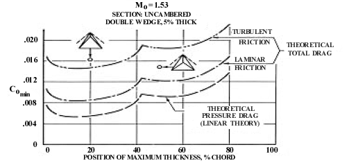
The exciting result of Puckett was then as follows: As the ridge line moves forward from the trailing edge, its sweep angle is at first less than that of the Mach cone, and the drag decreases somewhat. (The Mach cone defines the region of influence of a point disturbance in a supersonic stream; an example is shown by the dotted line from the forward point of the wings in the figure.) When the sweep of the ridge becomes equal to that of the Mach cone, the drag shows a sudden break in its downward trend; following this, the ridge has sweep greater than that of the Mach cone, and the drag decreases to a low minimum. This behavior suggested the possibility of reducing the drag by taking care in the design of the fore-and-aft section of the wing. When Puckett’s work appeared, our tests were in the planning stage, and we thought, “Let’s have a go at this and see if it works.” We therefore built and tested two triangular wings, one with ridge line at 50 percent of the chord and one at 20 percent, as indicated by the small drawings. The first thus had sweep less than that of the Mach cone, and the second greater.
To our surprise, the measured drag, as shown by the small circles, did not come out as predicted relative to one another. They were both above the theoretical pressure drag, as would be expected, since real wings have viscous drag tangential to the surface along with the pressure drag perpendicular thereto. The fact that the wing with ridge line forward had the higher drag, however, was contrary to Puckett’s finding. The natural suspicion, of course, was that this was also in some way due to viscous effects.
To think about this difficult matter, engineers resort to the concept of the “boundary layer.” This layer adjacent to a solid surface – the thin layer of air in which viscous effects are controlling – comes in two kinds: (1) a laminar boundary layer in which the air flows smoothly in lamina-like fashion, and (2) a turbulent boundary layer in which the flow is eddying and chaotic. The situation is rather like that of smoke rising from a cigarette in an ashtray in a very quiet room; it rises a certain distance smoothly, and then at some point becomes suddenly turbulent and chaotic. In much the same way, the boundary layer on a wing starts out laminar from the leading edge and at some point turns turbulent. The position of this transition point is crucial, since a laminar layer exerts much less frictional drag than a turbulent one. Transition depends on many things, however, and its location is extremely difficult to predict ahead of time. The best thing we could do to assess the situation was to calculate the added frictional drag, and hence the total drag, on the assumption of laminar or turbulent flow over the entire wing, as indicated by the middle and upper curves, respectively. We found, as can be seen, that the wing with ridge line forward had a measured drag slightly above the calculation for a completely turbulent flow; the other, with ridge line at midchord, fell about midway between the completely laminar and completely turbulent curves.
This was as far as we could go at the moment. Fortunately, I happened at this juncture to go to the laboratory library to browse through recent publications and came upon a report from the Royal Aircraft Establishment in Great Britain. There W.E. Gray had recently come up with something called a liquid-film technique for determining experimentally the extent of laminar and turbulent flow in a wind-tunnel test ( Gray 1946 ). He did this by coating the wing under test with a suitable liquid and then running the tunnel, causing the liquid to begin to evaporate. Now, just as a laminar boundary layer has a lower skin friction, by the same token it has a lower rate of evaporation than the turbulent layer. As a result, the coated surface dries off much slower where the layer is laminar than where it is turbulent. One, therefore, runs the tunnel until the more rapid drying of the turbulent layer appears to be complete and notes where the airfoil is dry and where it remains moist. The still moist area indicates where the boundary layer is laminar and the dry area where it is turbulent.
The British had devised and used the method at low subsonic speeds. We found that to make it work in our supersonic tunnel, as we immediately set out to do, took considerable adaptation. We spent a good deal of time – about a month – at the task. In the end, it came down to taking the two models, spraying them with flat black lacquer, and then coating them with a mixture of mainly glycerin. We then put the coated wing into the wind tunnel and ran it (as long as 20 minutes) until the rapid drying of the turbulent boundary layer appeared to be complete. We then removed the model from the tunnel, dusted it with talcum powder, and attempted to blow the powder away. It remained on the wing where the surface was wet (laminar layer), and blew away where the surface was dry (turbulent layer).
The results for our six-inch-span models were as shown in figure 2; the wing on the left had its ridge line at 20-percent chord, the one on the right at 50-percent. We see that the ridge-forward wing had only about one fourth of its area with laminar flow, whereas the ridge-rearward wing had about three fourths. This then corroborated our suspicion that the measured drag results were due to viscous effects. That is, since a laminar layer exerts less drag per unit area than a turbulent one, the lower total drag for the ridge-rearward wing now seemed reasonable.
Figure 2 Results of liquid-film tests of triangular wings at zero lift (minimum drag).
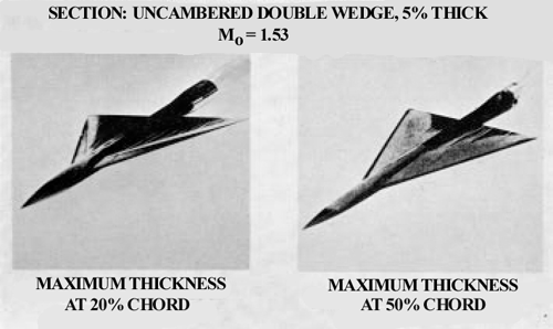
It was also consistent with known facts about boundary-layer behavior. Years of experience with subsonic flow had shown that laminar layers tend to exist where the pressure is falling on the surface of the airfoil as one goes from front to rear, and turbulent layers where the pressure is rising. In engineering terminology, a favorable (falling) pressure gradient keeps the boundary layer laminar, an adverse (rising) gradient turns it turbulent. When we examined the theoretical pressure distribution on the wings, which had been calculated in obtaining the pressure drag by Puckett’s theory, we found good correlation between the calculated areas of favorable and adverse gradient and the observed areas of laminar and turbulent flow. That is to say, the rising pressure over the larger, rear-facing area of the ridge-forward wing, which led to the lower pressure drag, resulted at the same time in a larger area of turbulent flow and hence a higher friction drag. The very thing that appeared from Puckett’s theory as something to strive for with regard to pressure drag actually proved detrimental with regard to friction drag. Thus, in the end, Puckett’s exciting result did not bear out in the real world.
This, then, is a typical story of how research engineers went about evaluating the reliability of theory as a design tool for calculating the performance of wings at supersonic speeds. We found that, even though a nonzero pressure drag existed and could be calculated (in contrast to subsonic speeds, where it is theoretically zero), the frictional drag was still critical. Design engineers would need to calculate the pressure drag and then, as at subsonic speeds, bring the knowledge gained in that process to bear on the frictional drag of the wing and somehow calculate that as well. As one might expect from an initial study, the present results were useful mainly for defining areas where further research would be needed if the theory was to become a useful design tool. Throughout, the knowledge we obtained as research engineers was very much conditioned by what design engineers would need for their practice.
Engineering Science
Let me say something now about engineering science ( Channell 1989, introduction ), which the foregoing story exemplifies. This category of engineering activity and knowledge comes into play if we ask ourselves, is what we have seen engineering or is it science? The following is an attempt to put the situation into visual terms as an aid to understanding. I have deliberately kept it simple – not overly so, I hope – but I believe it is basically valid.
What goes on in research in both science and engineering can be visualized initially as in figure 3. Here we have activities and knowledge (basic categories, as indicated by italics) interacting to produce more knowledge. Activities are of two kinds, experimental and theoretical, which interact with each other as well as with knowledge. In a given case, either experiment or theory can predominate or even be present exclusively. As in our narrative, both can also be present on more or less equal terms. As the overall interaction takes place, the knowledge involved will generally be both existing and emerging; the latter will usually appear gradually.
Figure 3 Initial visualization of research in science and engineering.
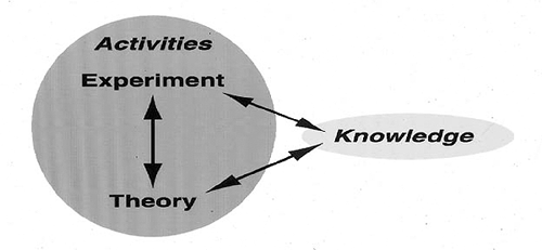
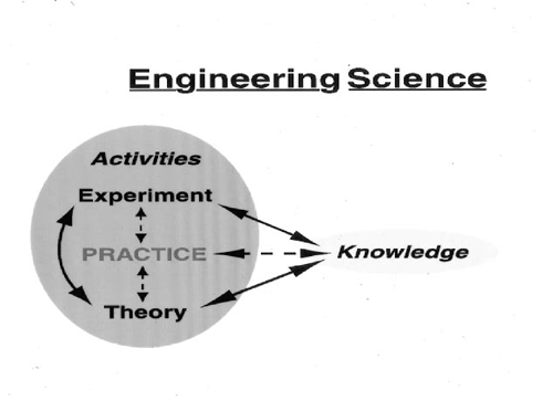
The figures show how one might visualize both scientific and engineering research to a first approximation. Further reflection suggests, however, that something is missing with regard to engineering. To understand this, let us look, not just at research, but at the full extent of science and engineering. Here the situation can be visualized as in figure 4. For science, nothing need be added to the previous diagram, since science and scientific research are one and the same and knowledge is their goal. The only change from figure 3 is the purely visual one that knowledge has been put in capital letters to emphasize its position as goal. For engineering, however, the situation is not so simple. In this case, though knowledge is involved, the goal of engineering as a whole lies in engineering practice, whether it be in design, manufacture, or operation (categories mentioned, incidentally, by Professor Pitt). Practice, as the word implies, is an activity – the major one in engineering. It uses and sometimes itself produces knowledge. It can also interact in various ways with experiment and theory, and this interaction can likewise produce knowledge. Knowledge, however, is not its primary goal. Practice must therefore appear among the activities in figure 4, where practice (not knowledge) is capitalized to reflect its being the fundamental goal. In the diagram, as in actuality, engineering is more complicated than science. Its philosophical study needs to reflect that reality.
Figure 4 Visualization of full extent of science and engineering.
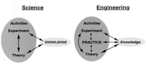
For the present we may ask, how does the research we have followed relate to the foregoing visual scheme? Is it – or was it – engineering or science? It was carried out in much the same way as scientific research, but was inspired by and had its goal in engineering practice; we recognize this when we speak of it and the kind of thing it typifies as “engineering science.” How can we represent this sort of thing diagrammatically?
Figure 5 provides a possible answer. The diagram here reproduces the engineering half of figure 4 except that practice is made fainter and its interaction arrows are dashed rather than solid. In our wing research, practice was not directly present, and the work could plausibly be seen as science; that is, if practice and its arrows in figure 5 are imagined to be so faint as to become invisible, we recover the science side of figure 4. In actuality, of course, practice was there, ghost-like, motivating and conditioning our activities – Ames Laboratory owed its very existence to the practical design needs of the aircraft industry. In the diagram, the goal of practice (again capitalized) is in fact present in the background, interacting with the other elements as in the engineering half of figure 4. Philosophically, what we term engineering science and see represented in the diagram of figure 5 conforms with what Michael Polanyi calls “systematic technology” in his book Personal Knowledge ( Polanyi 1962, p. 179 ). This, says Polanyi, “can be cultivated in the same way as pure science” but would “lose all interest” and fall into oblivion if the device or class of phenomena to which it applies should for some reason cease to be useful.
Figure 5 Visualization of research in engineering science.
In closing, a word of caution: Do not take the above diagrams too literally. Matters with regard to technology are usually messier and more complicated than the present graphical representations (or the historical example that inspired them). Remembering them helps me keep my epistemological thinking straight, however, and perhaps they can do the same for you.
References
Channell , D.F. 1989, The History of Engineering Science: An Annotated Bibliography (New York: Garland).
Gray , W.E. 1946, “A Simple Visual Method of Recording Boundary LayerTransition (Liquid Film),” Technical Note Aero 1816 (Farnborough: Royal Aircraft Establishment).
Polanyi , M. 1962, Personal Knowledge (Chicago: University of Chicago Press).
Puckett , A.E. 1946, “Supersonic Wave Drag of Thin Airfoils,” Journal of the Aeronautical Sciences 13, 475-84.
, W.G. 1949, “Comparison Between Theory and Experiment for Wings at Supersonic Speeds,” Second International Aeronautical Conference, New York – 1949 , ed. B.H. Jarck (New York: Institute of the Aeronautical Sciences), 534-55.
Vincenti, W.G. 2000, “Engineering Experiment and Engineering Theory: The Aerodynamics of Wings at Supersonic Speeds, 1946-1948,” Atmospheric Flight in the Twentieth Century, ed. P. Galison and A. Roland, to be published.